Network bonding
Network bonding enables the combination of two or more network interfaces into a single-bonded (logical) interface, which increases the bandwidth and provides redundancy. If a specific network interface card (NIC) experiences a problem, communications are not affected significantly as long as the other slave NICs remain active.
Bonding modes supported by RHEL and CentOS operating systems
The behavior of the bonded interfaces depends on the mode that is selected. RHEL supports the following common bonding modes:
- Mode 0 (balance-rr): This mode is also known as round-robin mode. Packets are sequentially transmitted and received through each interface one by one. This mode provides load balancing functionality.
- Mode 1 (active-backup): This mode has only one interface set to active, while all other interfaces are in the backup state. If the active interface fails, a backup interface replaces it as the only active interface in the bond. The media access control (MAC) address of the bond interface in mode 1 is visible on only one port (the network adapter), which prevents confusion for the switch. Mode 1 provides fault tolerance.
- Mode 2 (balance-xor): The source MAC address uses exclusive or (XOR) logic with the destination MAC address. This calculation ensures that the same slave interface is selected for each destination MAC address. Mode 2 provides fault tolerance and load balancing.
- Mode 3 (broadcast): All transmissions are sent to all the slaves. This mode provides fault tolerance.
- Mode 4 (802.3ad): This mode creates aggregation groups that share the same speed and duplex settings, and it requires a switch that supports an IEEE 802.3ad dynamic link. Mode 4 uses all interfaces in the active aggregation group. For example, you can aggregate three 1 GB per second (GBPS) ports into a 3 GBPS trunk port. This is equivalent to having one interface with 3 GBPS speed. It provides fault tolerance and load balancing.
- Mode 5 (balance-tlb): This mode ensures that the outgoing traffic distribution is set according to the load on each interface and that the current interface receives all the incoming traffic. If the assigned interface fails to receive traffic, another interface is assigned to the receiving role. It provides fault tolerance and load balancing.
- Mode 6 (balance-alb): This mode is supported only in x86 environments. The receiving packets are load balanced through Address Resolution Protocol (ARP) negotiation. This mode provides fault tolerance and load balancing.
IEEE 802.3ad Link Aggregation Policy and LACP
Before we explore LACP configuration, we should understand the IEEE 802.3ad link aggregation policy and LACP bonding, which allows us to aggregate multiple ports into a single group. This process combines the bandwidth into a single connection.
IEEE 802.3ad link aggregation enables us to group Ethernet interfaces at the physical layer to form a single link layer interface, also known as a link aggregation group (LAG) or bundle.
Some users require more bandwidth in their network than a single fast Ethernet link can provide. Using IEEE 802.3ad link aggregation in this situation provides increased port density and bandwidth at a lower cost.
For example, if you need 2 GBPS bandwidth to transmit data and have only 1 GBPS Fast Ethernet links installed on your system, creating a LAG bundle containing two 1 GBPS Fast Ethernet links is more cost-effective than purchasing a single 2 GBPS Ethernet link.
The following diagram illustrates the IEEE 802.3ad link aggregation policy:
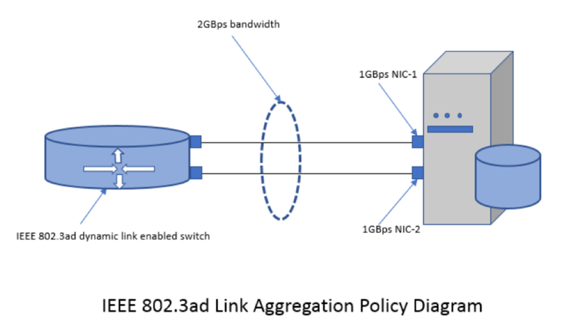
LACP is a mechanism for exchanging port and system information to create and maintain LAG bundles. The LAG bundle distributes MAC clients across the link layer interface and collects traffic from the links to present to the MAC clients of the LAG bundle.
LACP identifies the MAC address of the Ethernet link that has the highest port priority and is of the lowest value, and it assigns that MAC address to the LAG bundle.
This bonding mode requires a switch that supports IEEE 802.3ad dynamic links.